Only the female half of the servo extension cable is needed. Cut the female connector from the cable along with about 2″ of its wires. Solder its power and signal wires to the Feather’s Bat and D13 pins, respectively, and leave the ground wire unsoldered for the moment.
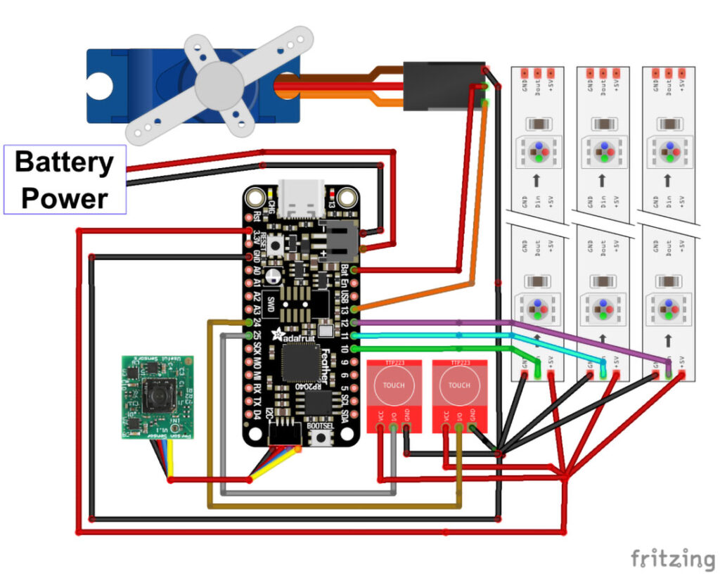

The wired connections between the Feather RP2040 and its peripherals are shown in Figure S. The Feather’s 3V and GND pins provide power for three LED strings and two touch sensors.
To simplify the connections, we’ll solder the peripherals’ power wires together in two bunches for power and ground, then connect each bunch to a single segment of solid core wire which then connects to a single Feather pin. Cut two 1″ lengths of 22 AWG solid core wire and strip about 1cm of insulation from one end of each wire. Group the 30 AWG power wires from the capacitive touch sensors and LED strings together, stripping about 1cm of insulation from their ends. Twist the stripped ends together. Do the same with the ground wires from the touch sensors and LED strings, including the servo cable’s ground wire in this bunch. When twisting the wires together, try to minimize tangling and knotting. Tin the twisted bunch of power wires, then solder it to the stripped end of one of the solid core wire pieces. Slide a piece of shrink tube over the joint and heat to shrink.
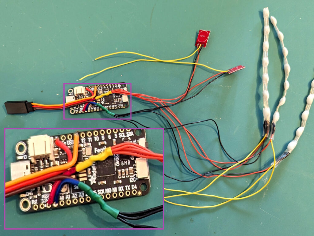

Repeat the same steps to connect the bunch of 30 AWG ground wires and the servo cable ground wire to the remaining piece of solid core wire. Finally, solder the free ends of the solid core wire pieces to the 3V and GND pins on the Feather 2040. At this point, the wiring should resemble Figure T.
Next, solder the free ends of the touch sensors’ signal wires to Feather pins D24 and D25, and the LED strings’ signal wires to Feather pins D10, D11, and D12.
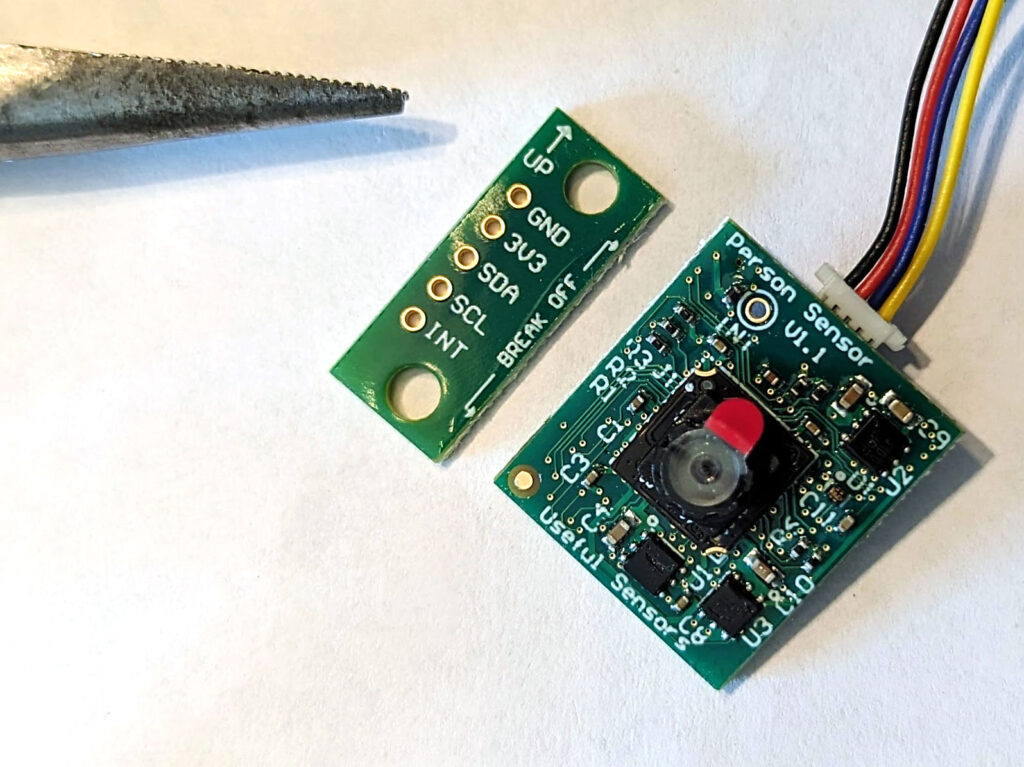

Take the Person Sensor, and carefully use pliers to snap of the portion of the board labelled “break off” (Figure U). Connect the Stemma QT cable to the corresponding connectors on the Feather and the Person Sensor.
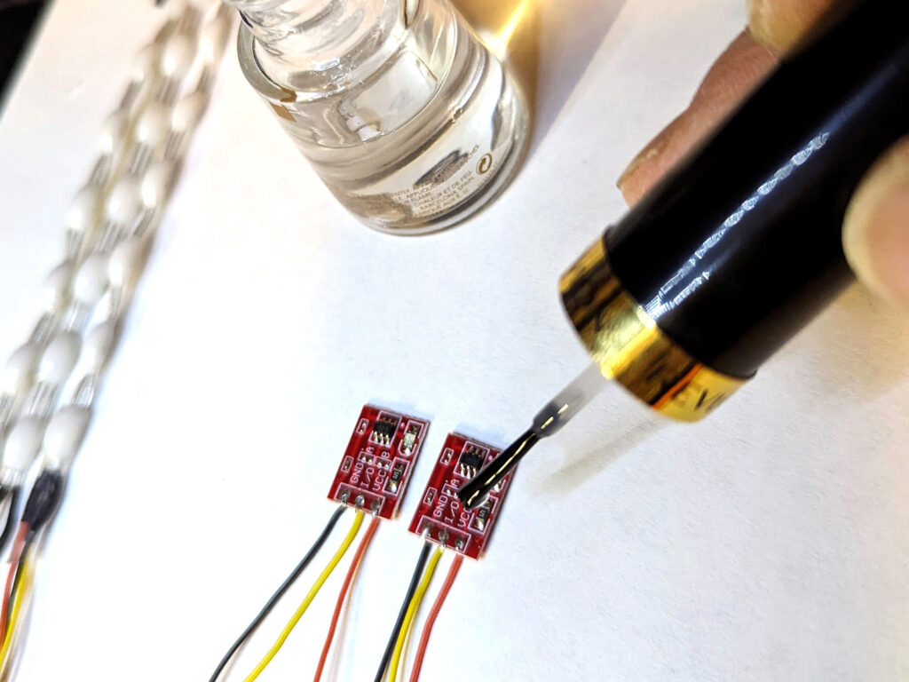

We’ll coat the sensor boards with clear nail polish for an extra layer of protection and insulation. Take the touch sensors and paint a layer of polish over the entire side containing the tiny SMT components (Figure V). Let the polish dry for 10 minutes. On the opposite side of the touch sensors, paint a bit of polish over the solder pins only, avoiding the portion of the board with the word “touch.”
Similarly, apply a coat of clear polish over the surface mount electronics on both sides of the Person Sensor, being careful not to paint the camera lens or the Stemma QT connector.
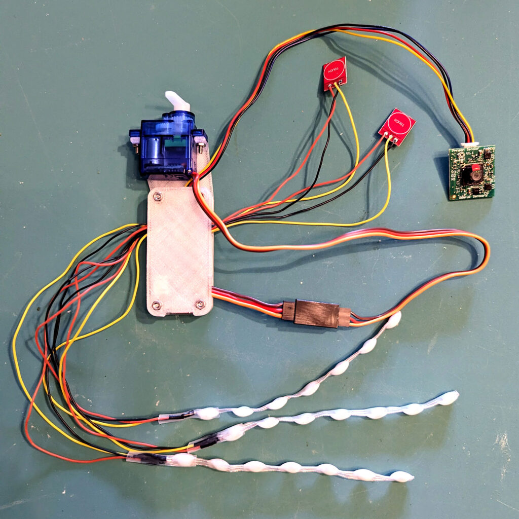

When the polish has dried thoroughly, insert the Feather into the 3D-printed enclosure, with the peripheral wires extending from the enclosure’s side holes. Secure the lid to the base with the four 12mm M2 screws and nuts as shown in Figure W.
Attach the micro servo to the two vertical prongs on the 3D-printed case with the 8mm M2 screws and nuts as shown. Orient the servo so its output shaft is centered along the short end of the enclosure lid. Attach the single-ended horn to the shaft so that the horn points directly upward in the middle of its rotation range, then screw the horn firmly onto the servo. Plug the servo connector into the female connector extending from the Feather.

