
Measuring temperatures is, along with making LEDs blink, a favorite first project for makers — but it’s a bit boring. Let’s make it do something!
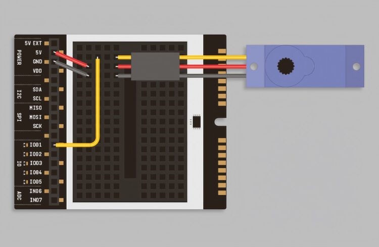
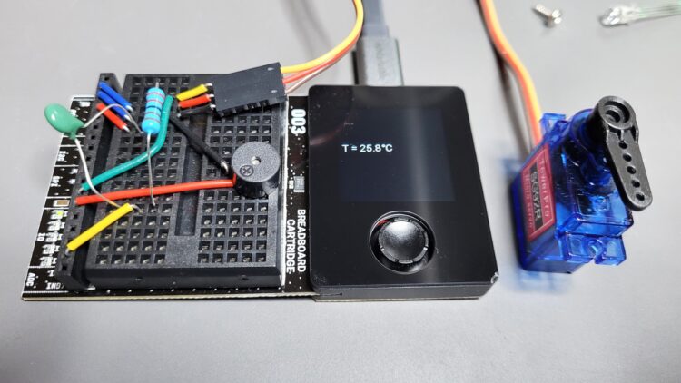
If you add a servomotor, you can physically react to the measured temperature, for example by moving a valve or knob, or the slats of a window blind.
Three lines are needed to control the servo:
setPWMFrequency(50)
dutyCycle = map(A, 90, -90, 102, 512)
writePWM(IO01, dutyCycle)
The first command sets the PWM frequency to the usual 50Hz for analog servos. The dutyCycle variable controls the servo angle, using a map() function to calculate the correct pulse width ratio, from 102 for 90 degrees to 512 for –90 degrees. (These values are derived from the Oxocard’s internal PWM frequency generation. Fortunately, everything’s already specified for you!)
Pass the result to our output pin IO01 using writePWM() and the servo is now set up. However, in order to move the servo linearly to the temperature, an additional call to map() is required, before the map() we just explained:
A = map(T, 40, 10, -90, 90)
dutyCycle = map(A, 90, -90, 102, 512)
This allows us to map our expected indoor temperatures of a maximum 40°C (104°F) to one full swing of the servo and a minimum 10°C (50°F) to the opposite swing. At 25°C (77°F) the servo should be approximately in the middle.


