For more than two decades, the long fiber injection (LFI) process has provided time, money and labor savings to manufacturers of glass fiber and polyurethane resin composite parts for markets such as transit, agricultural and construction. Today, composites experts from private industry, the military and higher education are working together to determine if LFI could also be used to produce CFRP components, manufactured in quantity and at a relatively low cost, for aerospace and other markets that require high-performance materials.
The research, which began in 2022, is funded by the Air Force Research Lab (AFRL). Participants include AFRL’s Manufacturing, Industrial Technology and Energy Division; Lockheed Martin, the prime contractor; equipment manufacturer KraussMaffei; and the University of Dayton Research Institute (UDRI). Romeo RIM, which has used LFI since 1999, is a consulting partner.
Process Variables
The current process for manufacturing CFRP parts for aerospace is long and labor-intensive. It often features prepreg materials that are manually placed on a single-sided tool, bagged and then rolled into an autoclave for a full day of curing. Debagging and trimming add to the production time.
LFI, by contrast, is fast, efficient and automated. After a chopper cuts fiberglass into the desired lengths (usually .5 to .24 inches), a mix head combines the chopped fiber with a two-part liquid resin, which is then sprayed into a preheated open mold. The mold is closed, and the part is cured using low-heat and low-pressure conditions. The entire process – one of the lowest cost and lowest waste composites manufacturing methods – takes anywhere from a few minutes to a few hours, depending on the part’s complexity.
To adapt the LFI process for carbon fiber, researchers are considering three variables –raw materials, equipment and robotic programming – according to Nicholas Gagliardi, senior research engineer at UDRI.
One concern the team had going into the project was debundling of the chopped carbon fibers. The fibers must disperse enough so that the resin wets them out in an even distribution during the mixing process.
“If that doesn’t happen, you end up spraying a slurry that has fibers clumped together. The result is highly porous or dry fiber regions inside your test panels, and the structural performance of those panels will be poor,” says Robert Koon, senior fellow at Lockheed Martin and the research program manager.
At one point the researchers changed the sizing of the fibers, but they debundled too readily and frayed as they were fed into the LFI mixing head. The team is currently leaning toward a carbon fiber from Zoltek that appears to offer the best combination of mechanical and debundling properties.
“It starts as a 50K tow, then the manufacturer breaks that tow down into much smaller 2K to 3K tows. Then they rewind those back together and re-spool them back to the 50k tow. They readily debundle when the chopping occurs at the LFI head,” says Koon.
“The carbon fiber system we’ve been using has shown really good promise, so I think in large part, that manufacturing risk area has been decreased,” adds Craig Neslen, manufacturing lead for Autonomous Collaborative Platforms in the Manufacturing, Industrial Technologies and Energy Division at AFRL.
Finding the right resin was another concern. “The baseline resin that Romeo RIM uses today is a Covestro polyurethane resin system. It is specifically designed to add air to the resulting cured panel to reduce its density, but in the process of doing so it also loses mechanical performance,” says Koon. “So, we use a higher performance polyurethane resin system in this program, and we are mixing it in a way where we minimize or eliminate the resulting potential void content in it.” They also ensure that the fibers and the resin system are degassed and dry before use.
“Another thing we are doing to improve the performance versus the baseline LFI process used in glass fiber applications today is slowing down the rate of the cure of the polymer so that we can spray larger parts and achieve higher fiber volumes,” says Koon.
Getting the Best Cut
On the equipment side, investigators are looking at variables that include cutting speeds, fiber lengths, fiber/polymer ratios, air pressure, press timings, mold designs and mold temperatures.
One major concern was the chopper’s ability to handle carbon fiber. “We evaluated the blades and the rollers and all the tubing and manipulation of the fiber to make sure, from a friction and wear standpoint, that the materials were adequate,” says Dan Rozelman, technical and sales application manager at KraussMaffei. The chopping blades were upgraded to a different material to get better results in cutting the fibers. The chopper is designed to cut up to four rovings at once.
The way the carbon fiber is rolled presented another challenge. The equipment was set up for glass fiber, which is pulled from the center of the roll. But carbon fiber is unrolled from the outside in.
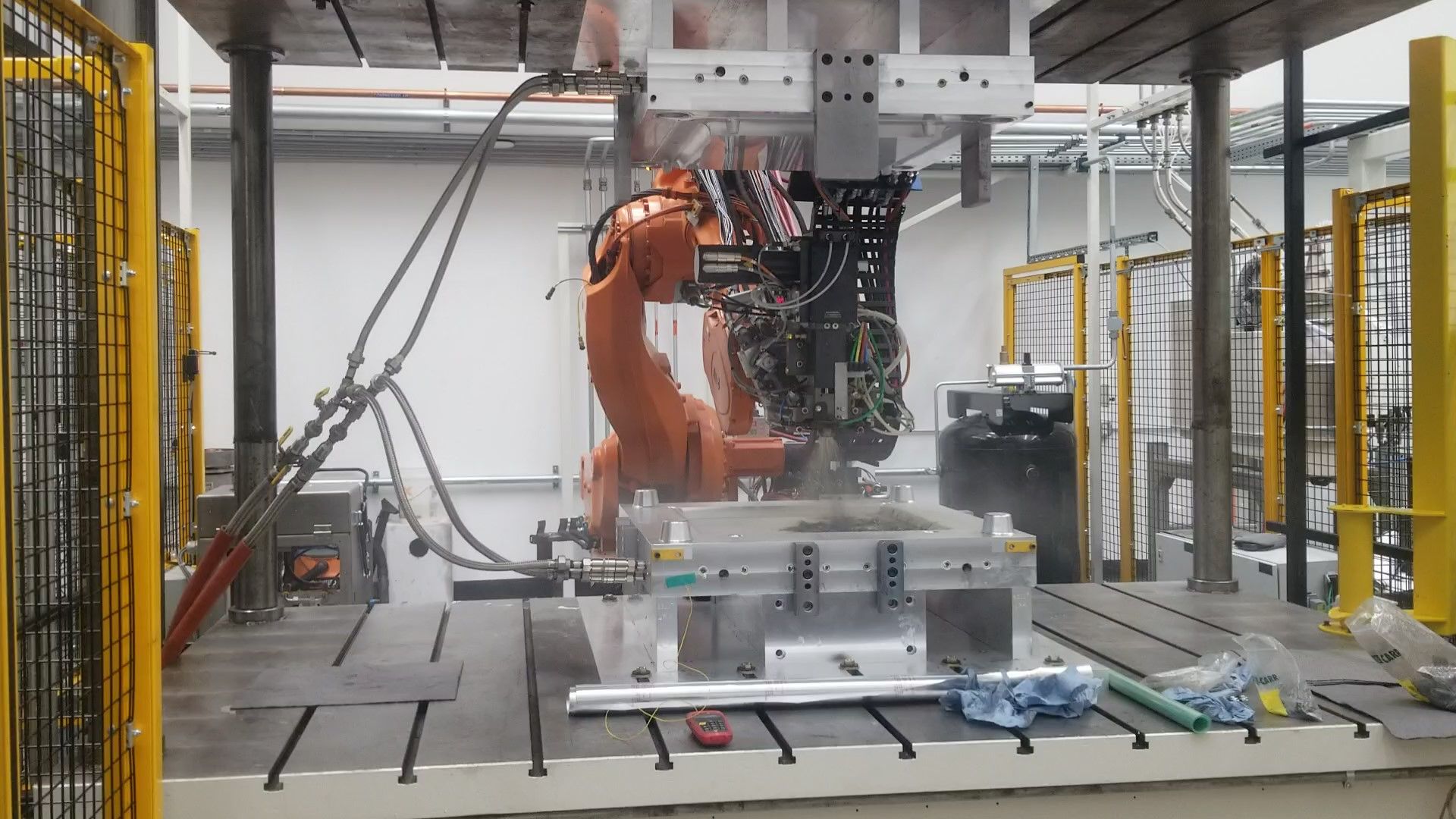
A robotic arm sprays slurry – chopped carbon fibers mixed with a polyurethane resin – into a heated mold as part of a long fiber injection research project. Photo Credit: University of Dayton Research Institute
“By cutting out the center tube from the carbon fiber roll we were able to pull from the center. These were minor changes, but they were significant to success,” says Rozelman.
Employees at KraussMaffei’s Munich headquarters provided further assistance by testing proposed changes on their equipment before they were made to the identical setup at UDRI.
“We worked on upgrades and on testing different knife angle configurations to see if we could achieve better cutting of the fibers and a long blade life,” says Rozelman. Additionally, KraussMaffei maintains a physical twin of the chopper in their headquarters in Munich for addition R&D and troubleshooting.
Researchers have also adjusted the path, speeds, angles and Z-height of the robotic spray arm. They tried different patterns of spraying the slurry to find the one that best maintains the consistency of the material’s properties across all regions of the part.
Panels to Parts
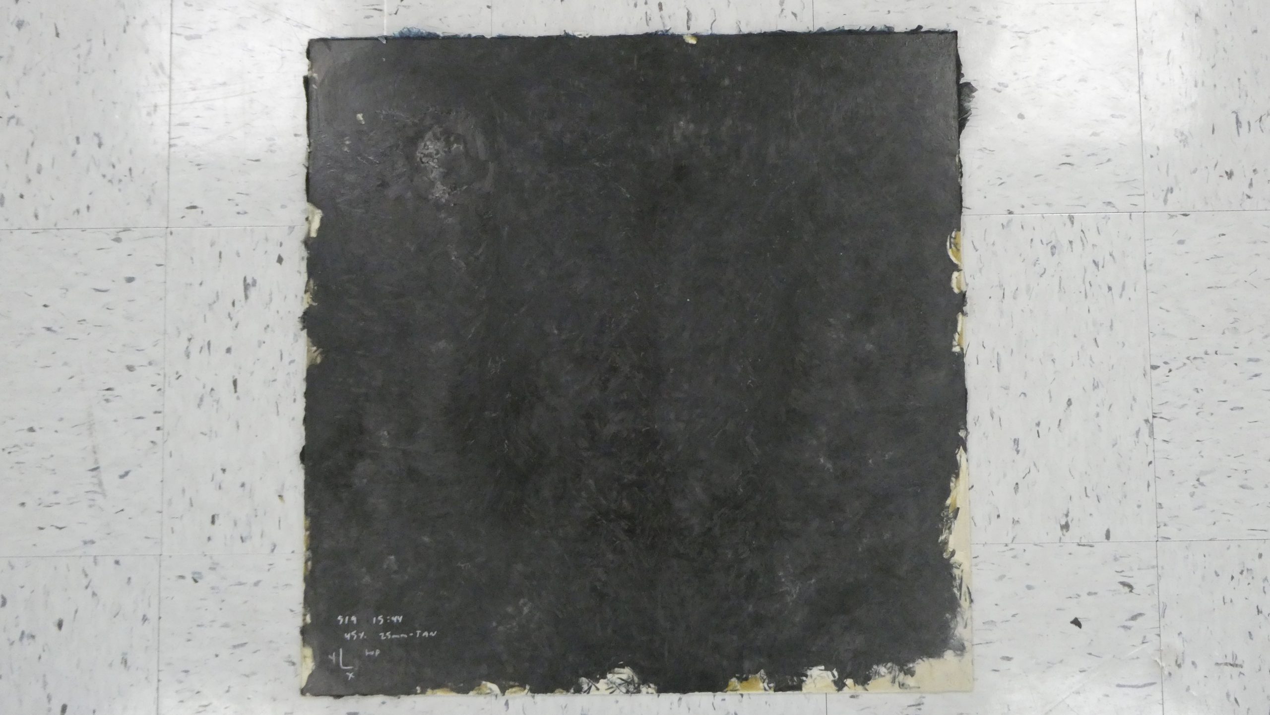
Project activities are taking place in a 4,000-square-foot research cell at UDRI. For the first production tests, Romeo RIM produced an LFI tool for manufacturing flat, 2 x 2-foot panels in three different thicknesses. UDRI is testing the panels per ASTM standards for tensile strength and modulus, short beam shear, compression and fiber volumes, according to Gagliardi.
Before the project wraps up at the end of 2025, the research team will produce two aerospace-relevant manufacturing demonstrations using the LFI/carbon fiber technology. The first, which will replicate rib sections for an aircraft wing, will use an existing tool from a previous AFRL/Lockheed Martin glass fiber LFI research project. Lockheed Martin and AFRL will select the final demonstration project and get a tool made so the team can manufacture and test the part.
Before fabricating CFRP demonstration parts with LFI, researchers made several test panels with varying percentages of fiber and polyurethane resin. Photo Credit: University of Dayton Research Institute
“The challenge is to reach the material properties’ goals that we have established,” says Neslen. “I think we’re well on our way to meeting some of those goals, but I think there’s still a concern if we’re going to meet them consistently.”
Although the polyurethane resin system is high-performance, Neslen says the team would prefer to use an epoxy resin because it would provide better properties. But that would require significant modifications to the LFI hardware system, and the funding isn’t currently available to cover those costs.
“If we can reach the intermediate material property goals with the polyurethane resin system, I think that opens the door to looking at epoxy resins later on,” Neslen says.
There are many other areas left to explore. “There is the potential to use it as an overmolding technique on continuous fiber preforms,” says Gagliardi. “Preforms could be used in areas that need the higher mechanical properties and LFI can spray in the open areas or on top of the preforms.”
Neslen says the Air Force could one day use this technology not only to produce parts for larger aircraft like future Group 5 Unmanned Aerial Systems (the largest and highest-flying UAS categorized by the Department of Defense), but also to fabricate components for vehicles designed to conduct a single mission, like missiles and strike vehicles. LFI carbon fiber technology could also be adopted by markets such as automotive, urban air mobility and heavy equipment, which would benefit from higher performance, higher speed, lower cost production.
In the meantime, Koon says the LFI carbon research cell at UDRI will be available to other groups that want to explore the possibilities of this technology.
“It’s the only carbon fiber LFI system where they can go and work in conjunction with UDRI to get comfortable with its benefits, its processes and its performances,” says Koon.
Cooperative research projects like this one can aid the entire composites industry.
“Developing and transitioning innovative composites technologies such as long fiber injection to the aerospace community benefits from collaboration with companies who are not traditional suppliers in the aerospace industry, in this case KraussMaffei and Romeo RIM,” says Koon. “Leveraging these companies’ innovations in low-cost composite processes accelerates the ability of aerospace OEMs like Lockheed Martin to find manufacturing solutions for our next-generation air vehicles.”
Mary Lou Jay is a freelance writer based in Timonium, Md. Email comments to mljay@comcast.net.


